From the point of view of the FKM guideline, the strength assessment for a rotating component is no different from any other assessment. For the user, however, there are a number of additional issues to consider. S-Life users have it a bit easier if they use the special features of our software.
The FKM guideline requires as input from the user for the cyclic assessmet, in addition to the material properties, a stress amplitude and the associated mean stress. This information can be provided in two different ways:
Extreme value of the stress σex,1 and the stress- or load ratio RLoad
In the vast majority of cases, a load case is characterized by the simulation of one extreme value of the load and the associated load ratio RLoad. For a single load, the load ratio is equal to the stress ratio for all points of the component. A typical example is a beam under alternating bending load. The first extreme value of the stress σex,1 is then obtained for each point of the component directly from the simulation, the second value σex,2 from the multiplication of σex,1 and RLoad. This also allows the mean stress σm to be determined. This procedure is useful as long as a load case consists of only one load or only proportional loads.
Two extreme values of stress σex,1 and σex,2
Often the stress ratio in the component changes depending on the position, for example due to a static preload, the superposition of several synchronous loads or due to nonlinearities in the boundary conditions (e.g. stops). In this case, a single simulation must be performed for each extreme value of the stress, which then provide σex,1 and σex,2 for each node of the component. For this case, S-Life offers the option to generate a so-called peak-to-peak load case from two FEM results. The local stress ratio R and the mean stress σm can then be calculated from the two stress tensors σex,1 and σex,2.
For a rotating component, the particular challenge is now to find the relevant extreme stresses σex,1 and σex,2 for each point of the component. Once these are known, an assessment can be performed as usual. In the following, three load situations and the corresponding procedures are discussed:
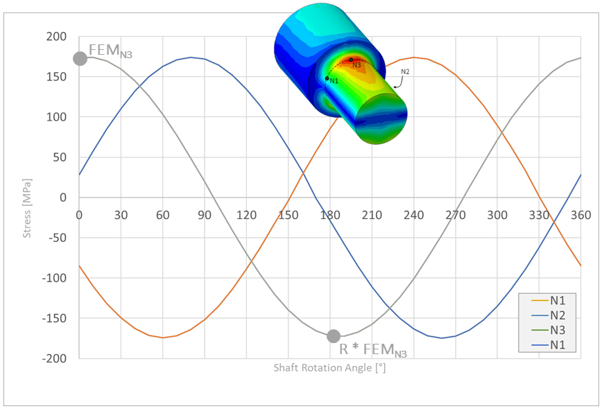
1. Unnotched shaft under rotating bending load
Figure 1 shows the snapshot of an unnotched shaft with constant, circumferential lateral force. As an example, three points on one circumference of the shaft were evaluated with respect to the local stress. It can be clearly seen in the diagram that the respective stress maxima and minima for the three nodes are identical, but are reached at different angles of rotation. Furthermore, the stress ratio is R=-1 for all nodes.
In the assessment, therefore, any position of the shaft can be considered. The contour plot of the stress ratios (which looks qualitatively the same as the stress plot shown in Figure 1) is then, strictly speaking, wrong, because all nodes on a circumference should actually have the same stress ratio. Only for the nodes at the top or bottom of the picture (N3) the correct maximum stress amplitude is determined here. For a technically meaningful assessment of the shaft, the value of the determined degree of utilization can be used without further ado, but the pictorial representation can lead to considerable misunderstandings.
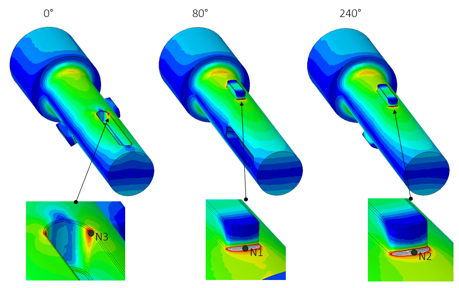
2. Notched shaft under bending load
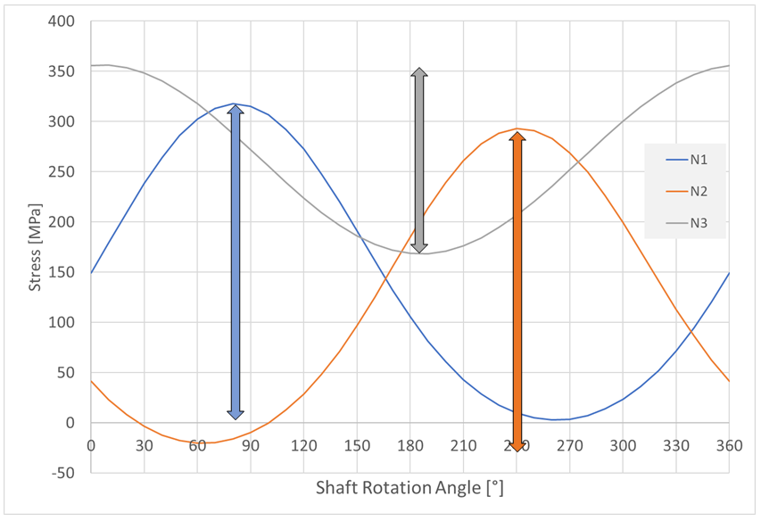
Figure 2 shows the identical load situation for an exemplary notched shaft. Depending on the angle of rotation, the stress state at the notches now looks different. Figure 3 shows the stress curves for three, possibly critical nodes.
Due to the pure alternating load, the stress ratio for all nodes is also the same here (σm=0, R=-1). However, with a single FEM simulation (here e.g. node 1 in extreme position) no meaningful assessment can be performed for nodes N2 and N3 because their stress amplitude cannot be determined. If obvious, the corresponding angular positions can be approached explicitly in a simulation (here 0° and 240°), otherwise the user only remains to run the rotation of the component in a suitable step size in the simulation.
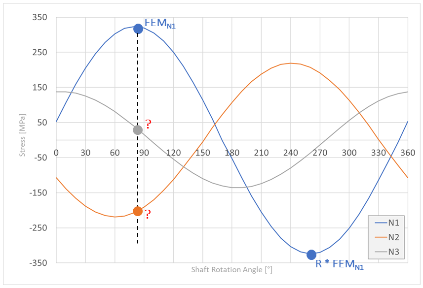
In S-Life, the corresponding simulation results can all be imported together as individual load cases. The same load ratio RLoad=-1 applies to all of them. The individual assessment for all increments is performed at the push of a button. In the assessment of each individual angular position, analogous to Figure 1, the nodes at the top (in the load axis /rotation axis plane) show the correct load ratio, while all other nodes are assessed with stress amplitudes that are clearly too low. To determine the maximum value of the degree of utilization in the entire component from the individual evaluations by comparison is tedious, and the graphical representation is unsatisfactory for a report.
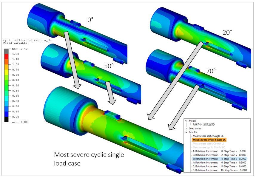
At this point, the evaluation option Most severe cyclic single load case represents a considerable simplification for the user. In this evaluation, the most critical degree of utilization is collected for each node across all load cases and displayed in a single contour plot on the component (drag pointer principle)(see Figure 4).
The angular increments in this procedure do not have to be equidistant. Depending on the course of the degree of utilization in a plot corresponding to Figure 4, additional angular positions can be added iteratively without any problems and included in the assessment until a sufficiently homogeneous gradient is obtained.
3. Notched Shaft with static preload and and circumferential bending load.
Figure 5 shows the stress curve of the three known nodes for the case of an additional, static preload, here a torsional moment on the shaft. Due to the preload, the nodes now have different mean stresses or stress ratios. In contrast to the previous example, the same load ratio cannot be assigned to all imported angle increments. Instead, the specific ratio must be determined for each node in each position.
To accomplish this in S-Life, a simulation of all angular positions that are to be assessed, each including the static preload, is necessary. It does not matter whether the preload is simulated first, followed by a transient simulation of the rotation, or whether the individual angular positions are simulated separately (torsion + bending).
Using the Peak-to-Peak Load Case Feature
To determine the correct amplitudes and mean stresses for each node of the component in each angular position, the Peak-to-Peak function in S-Life can be used. The stress states described above are combined in pairs, each rotated by 180°. That is 0° and 180°, 10° and 190°, and so on. It must be assumed here, that the maximum amplitude is always reached in opposite positions.
With a 10° incrementation of the rotation, a total of 18 peak-to-peak load cases are created from the 36 individual load cases, in which the correct mean stresses and stress amplitudes are automatically determined for each node. (The use of material-fixed coordinate systems in S-Life eliminates the rotation of the component).
The individual load cases can then be assessed analogously to the previous procedure and evaluated using the Most severe cyclic single load case function.
Here, too, increment pairs x° and x+180° can be added successively, if necessary.
Depending on the complexity of the system under consideration, the assumption that the critical stress amplitudes each occur between 180° rotated angular positions is no longer permissible. In this case, the number of possible peak-to-peak combinations is considerably higher and can no longer be reasonably handled manually. Figure 6 shows this schematically for a 45° incrementation of the rotation. In the upper part of the figure, the procedure described here is sketched assuming a 180° pairing. In the general case (lower part of the picture), all possible angle combinations would have to be proven and evaluated according to the drag pointer principle. We are currently working on this and will report on it in due course in a second part of this blog.
Author
Dr. Marcus Stojek is Managing Director at PART Engineering GmbH, Bergisch Gladbach, Germany