by Dr. Domen Stadler
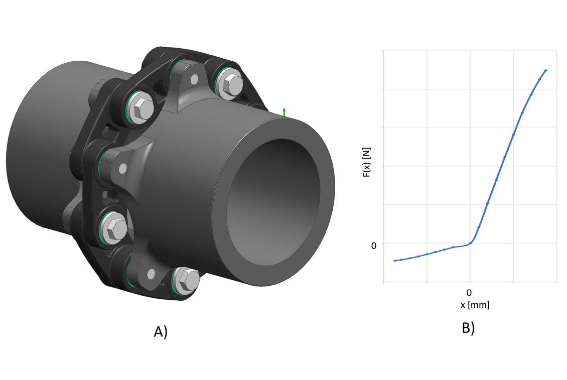
Elastic couplings of SGF are frequently used in diverse industries like automobile, power and manufacturing. The use of such couplings reduces vibrations and compensates axis misalignment, while at the same time improves the fatigue strength of the complete machine. S-Life FKM by PART Engineering [1] is an easy-to-use software, in order to assess the metal parts according to the FKM guideline [2]. As such, it can be used for the metal parts of the elastic couplings, namely for the flanges. The challenge that arises by the elastic couplings is the nonlinear characteristics of the link elements, the relative rotation and the large cycle number of the radial load (Figure 1).
These two peculiarities of the elastic coupling do not allow the usage of the superposition principle of loads. This implies, that every possible combination of loads (axial force, radial force and torsional torque) must be separately considered, resulting in a large number of load cases and consequently large number of strength assessments. The simple assessment of the superimposed stress states, resulting from a single unit load, would lead to false results. Normally the assessed result will falsely show a higher component strength as in reality, possibly resulting in a failure of the part. For this reason, all load combinations must be simulated and subsequently assessed against the fatigue strength accordingly. With a wise choice of the critical load combinations the fatigue strength assessment can be reduced to two load combinations.
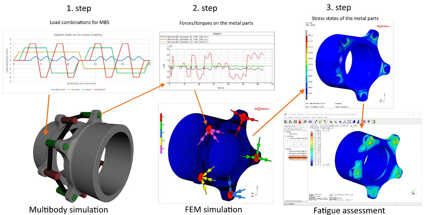
The depicted method (Figure 2) is performed in three steps. In a first step the actual forces and torques applied to the metal flanges resulting from the loads on the coupling are determined by means of a multibody simulation for every possible load combination. These forces and torques are then in a second step transferred to a FEM analysis in order to determine the stress states for each load combination. In a third step the appropriate load combinations are determined and a static and fatigue strength assessment according to the FKM guideline is conducted with S-Life FKM.
The MSC Marc FEM software is used to perform the FEM analyses due to the simple table-driven load definition. With this approach it is possible to compile all possible load combinations in tables, one for each force and torque direction respectively. All possible load combinations are therefore simulated by a single FEM-load case with the usage of such tables. This compiled load case has multiple load steps and each load step corresponds to a single load combination on the complete coupling. The transfer of forces and torques from the MBS software to MSC Marc is done with the help of scripts, resulting in a very simple and fast process for the first two steps of the strength assessment.
With the new hdf5 interface in S-Life FKM it is possible to perform the third step of the strength assessment, namely the assessment of the metal parts according to the FKM guideline. The interface provides the capability to read and assess the FEM results load step-wise, meaning that each load combination can be separately assessed. Nevertheless, the choice of the assessed load steps must be meaningful and plausible.
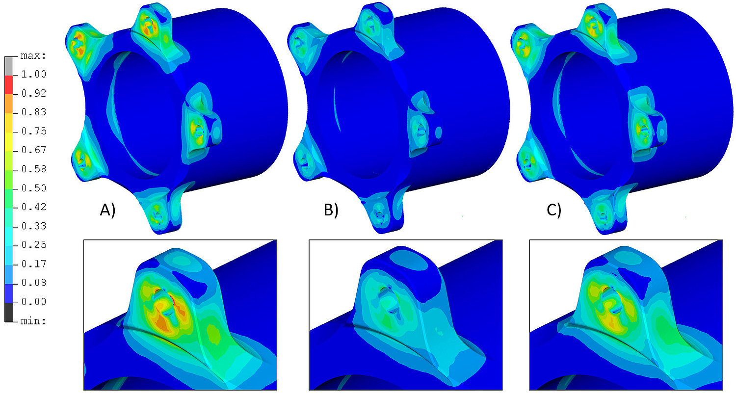
If the FKM assessment is to be made for a single load step with the overall maximum of the equivalent von Mises stress and this load is assumed to be fully reversed, the assessment’s result will be to conservative due to the nonlinear characteristics of the link element. The metal parts will withstand the required loads, but they will be over-dimensioned. A second approach is to assess the same load step, but this time with the assumption of a purely pulsating load. This approach could again lead to the false positive result as is the case with superimposed stress states, resulting from single unit loads.
The determination of two load steps (for P2P) must be such, that the difference between the stress states of all simulations is the largest possible. The first load step can be easily determined by the overall maximum of the equivalent von Mises stress. The determination of the second load step is based on the bending nature of the stresses in the flange’s arm due to the loads of the link element. The load of a single link element is not linear. Even though the torsional load as a whole is acting monotonically on the stress state in the flange. With other words, if the torsional load is larger, so are the resulting stresses in the flange. Additionally, if the torsional load changes its direction the nature of the stresses (tension vs. compression) in the flange also changes. Analogous conclusions can be made also for an axial and for a radial load of the coupling. When it comes to the superimposed loads, one should keep in mind, that the torsional load is the prevalent load. The axial and the radial load only “shifts” the value of the maximal stress (nonlinear), but the distribution remains the same. A comparable effect can be observed, when the bended beam is additionally loaded with a normal force. The position of the max. stresses remains the same, the distribution of the stresses also, only the values are shifted.
Based on these conclusions the determination of the second load step is done simply by changing the directions of the loads. The remaining question is the actual rotational position of the radial load, since this load shows the largest nonlinear effects in terms of the stresses. Again, the bending nature of the stress state helps to answer this question. It ensures that the sought rotational position of the radial load is the one that has the highest equivalent stress within the load steps with the reciprocal load directions to the first chosen load step.
The bottom line is that such an approach increases the chance to assess the fatigue strength with a single P2P-analysis of two load steps. For this purpose, the already implemented P2P-analysis tool and the new hdf5- interface within S-Life FKM come to a great advantage in the prediction of the fatigue strength for the metal flange of the investigated coupling under rotating loads. With such an approach, the whole simulation procedure is reduced very smart to a single multibody simulation, a single FEM simulation and a single fatigue strength assessment with S-Life FKM. Thus, the required engineer’s time and interaction are also reduced as well as the sources of possible errors and misinterpretations of the results.
[1] Strength Assessment According to FKM Guideline, S-Life FKM Documentation V3.7, PART Engineering, Bergisch Gladbach, Germany
[2] Rechnerischer Festigkeitsnachweis für Maschinenbauteile, FKM-Richtlinie, 7. Auflage 2020, VDMA Verlag, Frankfurt, Germany