When integrative simulation is mentioned in the context of the design of technical plastic components, it usually refers to the consideration of local fiber orientations. Although this is certainly an important aspect for the computational design, the filling simulation provides a range of additional information and data which can and should also be taken into account in the further development process. The integrative consideration of the manufacturing process with all influences on the component and tool development offers considerable added value with comparatively little effort.
Material Properties
The consideration of the local stress (mostly stresses) in the component under a certain load is the procedure for the evaluation of an FEM simulation, which is surely familiar to everyone. Scaled to the allowable stresses from the data sheet, the "red" areas indicate critical regions. Unless the allowable stresses were different at each point of the component....
And this is exactly the case. For example, weld lines reduce the local component strength significantly (by off in the range of 50%). An FE model that does not include the position of the weld lines cannot reproduce this effect, of course. The consequence is that critical areas are overlooked. Figure 1 shows the simulation result of a bending test with the typical hot spot in the center of the component. In the test, however, the failure occurs at a different point, namely at the weld line. What still appears to be avoidable here in a simple example quickly becomes uncontrollable with complex geometries, filling patterns and different load cases. With our tool Converse, the weld line positions from the filling simulation can be transferred to a structural model at the push of a button and special material properties can be assigned. In this way, critical stresses in the weld line become directly visible during evaluation.
The same applies to the direction-dependent strength of fiber-reinforced plastics. For more information on this aspect of integrative simulation, please refer to our Converse documentation. Among other things, our product S-Life Plastics supports you in the evaluation of stresses in anisotropic materials.
Geometry
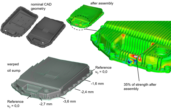
In addition to the material-related data, the filling simulation also provides data that can be assigned to the component geometry. The most obvious example is component distortion. Whenever an injection-molded component has to be assembled or welded, the deviation from the nominal geometry leads to additional forces (and/or deformations) in the system. Especially with highly rigid materials (GF40+), it can be very advisable to get an idea of the resulting force level. Also for this purpose, Converse can be used to transfer the component distortion to the FE model of the CAD geometry and to perform the assembly simulation with the distorted component. Figure 2 shows the example of an oil pan which, after assembly has already consumed over 30% of the material potential due to deformation load.
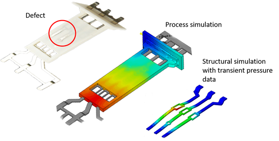
Geometrical deviations in the component can have a completely different cause when it comes to inserts or back-molded foils. Here, permanent dimensional deviations can occur due to deformations caused by the melt pressure. However, the pressure load of the melt on such components is calculated in the filling simulation anyway. After transfer to a corresponding structural model, the deformation of the overmolded components or the formation of wrinkles in decorative elements can be predicted with a high degree of certainty and eliminated by various measures. Figure 3 shows such a defect pattern using the example of wires pressed against the component surface.
Mold and inserts
The same effect can lead to premature failure in the mold if slender segments, cores or slides in the mold are deformed by the melt during filling or when switching to holding pressure. The resulting stress peaks with each shot can lead to breakage even after relatively low numbers of cycles. All data are actually available for this case as well. The pressure curve over time on the mold wall as well as the mold geometry itself. If detected at an early stage, such problems can often be avoided with relatively simple measures.
These brief examples should have made clear the importance of process data, which are usually available anyway, for design and development. Especially if structural and injection molding simulation are already (separate) parts of the development process, the effort required for integrative simulation with Converse and S-Life Plastics is manageable, but the benefits can be considerable.
Author
Dr. Marcus Stojek is Managing Director at PART Engineering GmbH, Bergisch Gladbach, Germany