The high pressures during injection molding can lead to premature mold failure if slender segments or cores are deformed by the melt during filling or when switching to packing pressure. The resulting stress peaks can lead to breakage of cores after only a few cycles. All the necessary data to take this into account in the simulation are usually available, since injection molding simulation is already state of the art for the development of plastic parts. If such a problem is detected at an early stage, it can often be avoided with simple measures. The effort for a holistic simulation is manageable, but the benefits can be considerable.
Problem
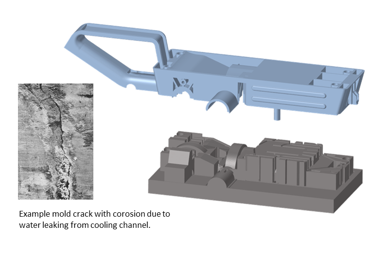
For demonstration purposes, a section of a mold for manufacturing a housing for a belt grinder is used. This example is inspired by practical cases with broken cores. Often such a problem occurs only after many thousands of cycles. It only becomes visible, for example, when cooling water leaks out because the crack has migrated inwards from the cavity surface without the core as a whole having failed. Once detected, replacements must be made and production of the plastic part must be interrupted for a period of time. This is not desirable from a financial point of view, among other things.
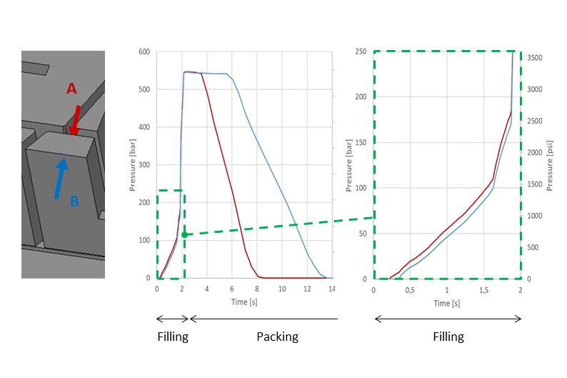
Injection molding simulation is often an integral part of the development process. It is possible to study in detail how the melt flows in the mold and how the melt pressure affects the mold as a whole and the individual cores. To get a realistic picture of the pressure load, it is not sufficient to look at a discrete point in time. Rather, the pressure must be considered over the entire process. Each position in the mold is subjected to different pressures at different times. This must be transferred to the mechanical simulation. Converse is used for this purpose. Figure 2 shows the filling of the part on the left and a section of the mold on the right. Converse transfers the pressure profile over time from the injection molding simulation, which only depicts the molded part (Figure 2, left), to the corresponding structural model of the mold for the simulation of the mechanical behavior (Figure 2, right). At the end of this mapping, each finite element of the structural model that has been in contact with the melt receives an individual pressure profile over time. This data is provided as a human-readable file to make its use in the respective FEM program for structural simulation as simple as possible and to enable seamless integration of the process into existing software infrastructure.
Pressure differences
Critical areas are usually slender structures without support. The highest loads occur on a core when the melt does not act uniformly on all surfaces of the core. The unilateral loads then lead to deformations and corresponding stresses in the notch root at the core base. If the melt flows uniformly over the core from the tip, the pressures approximately cancel each other out. It is therefore the pressure differences that lead to core failure. Figure 3 shows the pressure amplitudes on both sides of the core under consideration. Side A is closer to the gating point than B, so the pressure loading starts earlier here, resulting in a pressure difference during the filling process. By far the greater pressure difference, however, occurs in the packing phase. In the filling phase, there is either liquid melt or air in the mold. Neither can support the core. After the filling phase has ended, the packing pressure phase begins. The core is then completely surrounded by melt, some of which has already solidified and thus at least hinders deformation. To properly account for this effect, a coupled analysis would have to be performed that also considers the freezing of the melt and supports the core. In particular, if the pressure on side A drops to zero, it must be assumed that the melt has solidified from that point on and that no further pressure is acting on this side of the core. In this example, only the pressure during filling is considered. In the structural simulation, the transient pressure curve transferred by Converse is considered in the simulation by an appropriate choice of time step size. S-Life FKM is used to perform a fatigue strength assessment for the desired number of cycles. For this purpose, the FEM result file with the computed stress history per finite element is imported. Interfaces to different FEM programs are available.
Strength assessment
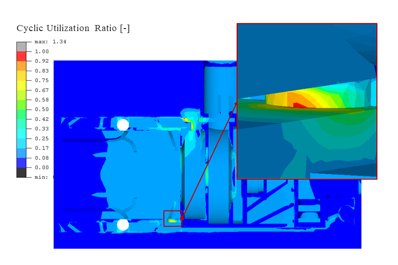
In addition to the selection of the mold steel and, if necessary, temper conditions from the database contained in S-Life FKM, some information on the load case must be entered. After that, the analysis can be started and the assessment according to the FKM guideline will be performed for the entire mold and a resulting utilization ratio will be displayed. Figure 4 shows the result of the fatigue strength assessment. The critical area is shown enlarged here. The legend represents the cyclic utilization ratio. For ratios greater than one or 100 % and taking the safety factor into account, the strength assessment is not satisfied. Here, the critical area has not quite reached 100%. However, the result shows that the probability of failure can be reduced with a small design optimization such as a radius at this point.
Conclusion
Core failure is time-consuming and costly. However, it can be predicted by simulating the pressure loads on the core during injection molding and a subsequent fatigue strength assessment. Suitable design measures such as larger radii can then be considered in advance. More even pressure distribution on the critical core through better gate positioning or the insertion of flow aids or flow retarder can also help. With Converse and S-Life FKM, efficient software tools are available to avoid core failure by using simulation as early as the mold design stage and to ensure robust injection molding production later on.
Sascha Pazour, FEA & Software Sales Engineer at PART Engineering GmbH, Bergisch Gladbach