To keep the development costs for injection molded components as low as possible, meaningful prediction methods are required. It is state of the art to describe the manufacturing process in a so-called process simulation and then the finished component design with the FEA.
An important aspect of process simulation is the prediction of fiber orientation and weld lines for short fiber reinforced polymer composites. These have a significant influence on the mechanical properties of the component.
The formation of weld lines is almost inevitable in components manufactured by injection molding, when two different melt streams are combined or when the melt stream flows around an obstacle. The structure of the component, at the position of the weld lines, differs from the structure of the rest of the component. For example, in fiber-reinforced plastics, the fibers arrange themselves parallel to the weld line but do not cross it. In contrast, the fibers in the rest of the component arrange themselves parallel to the flow direction.
The resulting weld lines represent a potential weak point of the component. Tests on test specimens allow tensile strengths to be determined, which serve as material parameters for characterizing weld lines. An integrative simulation method makes it possible to transfer weld line positions from a filling simulation to the structural simulation, where the anisotropic stresses can be represented.
Influence of the geometry on fiber orientation at the weld line
The material parameters used in integrative simulation are obtained almost exclusively from tests with standardized test specimens made of plates. Also weld line situations can be mapped with this method. However, the important aspect of a possible geometry dependence of the formation of the fiber orientation at the weld line is neglected. In preliminary investigations of the Kunststoff-Zentrum in Leipzig gGmbH, hereinafter referred to as KUZ, results of the process simulation indicate a geometry dependence of the fiber orientation (see Figure1).
Aim of the research project
The aim of the research project is to prove a geometry dependence of the fiber orientation in the weld line area of short fiber reinforced plastics and to derive from this a corresponding need for action to determine resilient material properties for use in integrative simulation:
- Development of suitable test specimen geometries that can represent application cases for the formation of weld lines in a practical manner
- Investigation of the suitability of the developed test specimen geometries for the determination of mechanical properties using standardized test methods such as tensile or flexural tests
- Validation of the test methodology and integration into the integrative simulation process
- Validation of the results of the integrative simulation on test specimen geometries on real measured morphological data and mechanical properties
The aim of the fundamental investigations is to optimize the iterative design in the development process of fiber-reinforced molded parts by means of simulative methods, considering the anisotropy occurring in the weld line area due to processing technology, and to shorten the iterative process by providing resilient material parameters. By taking the geometrically dependent fiber orientation into account in the FEA, it is possible to prevent over- or undersizing of the molded parts.
Integrative simulation
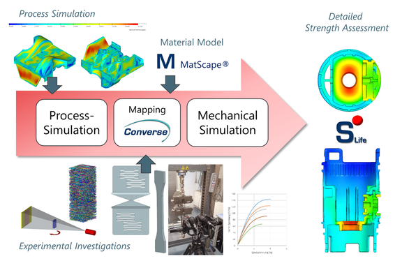
A fiber-reinforced component shows anisotropic properties. These must be considered in the structural simulation. For this purpose, the results of a filling simulation, in this case the fiber orientation tensor, are transferred from the mesh of the filling simulation to the mesh of the structural simulation. For this purpose, the KUZ is using the Converse software in this project.
Thermoplastics and fiber-reinforced composites exhibit considerable complexity in their properties, both in terms of processing and structural behavior. When designing components made of short-fiber-reinforced plastics, it is necessary to consider not only the dominant characteristic, locally anisotropic material properties, but also other influencing factors such as multi-axial stress states, high stress gradients or medium stress sensitivities. The S-Life Plastics software can do this.
The realistic simulation of unreinforced or short-fiber-reinforced plastic components under mechanical and thermal load requires a detailed description of the material behavior in the form of a material card that can be used in FEM programs. For the creation of such material card, experimentally determined material parameters as well as microstructure information must be prepared and adapted in a software-specific and application-specific manner. The KUZ is using MatScape for this project. After validation of the created material model, it can be used for the design of components and thus contributes to the reduction of development times.
This approach achieves a significantly more precise strength prediction than is possible with the common isotropic material models in structural simulation.
Simulative analysis of weld lines
In fundamental research, the mechanisms of weld line formation and their molecular effects on strength have been studied in more detail in order to make better strength predictions. Nowadays, more accurate predictions of weld line strength can be made via modern integrative methods.
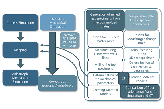
In preliminary considerations, the geometry dependence of fiber orientation on weld lines will be demonstrated via filling simulations. The simulative proof will then be confirmed by practical tests with testing on suitable test specimen geometries. The KUZ carries out basic investigations on the relationship between the morphology (fiber distribution, fiber orientation) and the mechanical properties of the developed test specimens. At the same time, the morphology of the test specimens is examined and characterized by means of CT. The fiber orientation and fiber distribution determined in this way are compared with the results from the filling simulations. Subsequently, the mapping of the fiber orientations, as well as the structural simulation is performed. The results are compared with the tensile and flexural tests of the real test specimens. Different test specimen geometries are considered in the integrative procedure. On the one hand, suitable standard test specimens for tensile and flexural tests are mechanically extracted from injection-molded sheet material behind flow obstacles of different geometry. On the other hand, 3D test specimens specially developed for the investigations will be examined and characterized in tensile and flexural tests. During the project, the following plastics will be comparatively included in the investigations:
- Polyamide 6
- Polyamide 6 GF10
- Polyamide 6 GF40
- Polybutylene terephthalate (PBT) GF30
The results obtained will be compared and evaluated to determine whether the new 3D test specimen geometries allow more precise determination of material data for problems arising in practice. Figure3 shows the procedure planned in the project.
The following questions are to be addressed in the investigations of the project:
- Is there a geometry dependence of the fiber orientations during the formation of a weld line?
- Does this result in a different influence on strength in the weld line area?
- How can this influence on strength be demonstrated in practice?
- Is it possible to find suitable 3D test specimen geometries for the verification of the geometry-dependent strengths?
- Is it possible to safely establish a process routine using integrative simulation to account for the geometry-dependent strengths in the weld line area?
- Is it possible to establish suitable material cards for the geometry-dependent area for structural simulation?
Development of suitable 3D test specimen geometries
From a practical point of view, the KUZ is aware of cases of damage to weld line formations of fiber-reinforced molded parts primarily in geometrically tubular bodies. Therefore, the focus of the investigations is to be placed on this geometric design.
In a variant conception, suitable test specimen geometries are to be determined which generate different fiber orientations at the weld line regarding the investigations on geometry dependence. At the same time, attention must be paid to the requirements of the subsequent test procedure in the tensile and flexural tests to be able to determine representative material characteristics at the measuring point of the weld line. The geometries should allow the variation of the wall thickness and the angle of impact α of the melt fronts (see Figure4) for different tests.
Relationships between morphology and mechanics
Integrative simulations are carried out for all variants of the test specimens. For this purpose, filling simulations are made at the beginning. The results are then compared with those of the tests on the real specimens and the deviations quantified.
- Fiber orientation from CT and filling simulation
- tensile and flexural stiffness from the tests and the structural simulation
It is expected that there will be deviations between simulation and practice. In this case, the material card will be corrected and subsequently the simulations will be re-run and re-tested. It will be evaluated which variables have a significant and which have a minor influence on the correlation.
Summary and outlook
Up to now, the material parameters used in integrative simulation have been obtained almost exclusively from tests with standardized test specimens. Unfortunately, no investigations exist that clarify the correlation between the geometry of a flow obstacle, the locally forming fiber orientation and the weld line strength present at this point.
In this project, the geometry dependence is to be demonstrated by testing specially developed 3D test specimens with a forced weld line. For this purpose, the corresponding material parameters are determined on the test specimens, which form the basis for a more precise model in the structural simulation.
Author: Steffen Jacob, Development Engineer, Kunststoff-Zentrum in Leipzig gGmbH, Leipzig, Germany
Co-author: Sascha Pazour, CAE and Sales Engineer, PART Engineering GmbH, Bergisch Gladbach, Germany


