Consider Component Manufacturing
What is Converse?
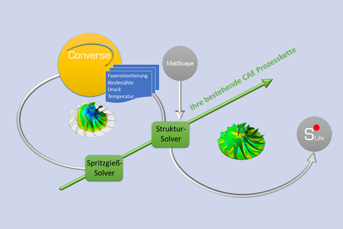
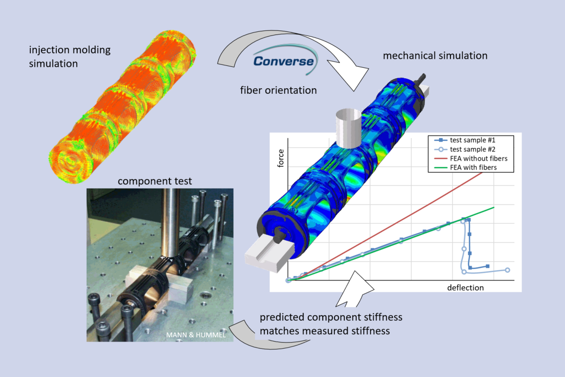
Converse is the process-structure coupling software within the PART software suite. Converse links manufacturing simulation with structural simulation. Data obtained within a manufacturing simulation can be easily transferred into a model for a structural simulation. In interaction with MatScape, Converse enables a multiscale simulation approach for fiber-reinforced plastics by transferring material properties obtained with MatScape at the micro level to the macroscopic component level.
In interaction with S-Life, Converse provides strength-relevant information from the process, such as weld line position and fiber orientation.
In addition, further component or tool-relevant data such as pressures, temperatures and shape deviations can be processed
The Problem
Lack of consideration of manufacturing
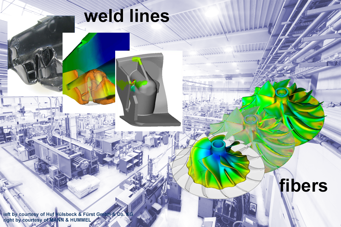
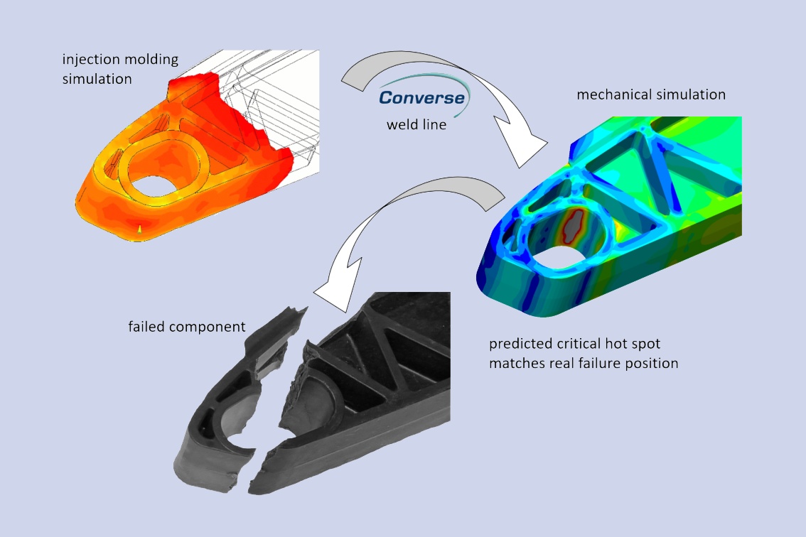
Manufacturing influences such as fiber orientation and weld lines are not considered in structural simulation. However, these usually have a considerable influence on the mechanics of the component. The result is over- or undersizing. One reason for not taking them into account is often that the necessary coupling of an e.g. injection molding simulation program with a structural simulation program is laborious. Furthermore, in the case of fiber orientation, the required direction-dependent material parameters are often missing.
Unexpected manufacturing problems
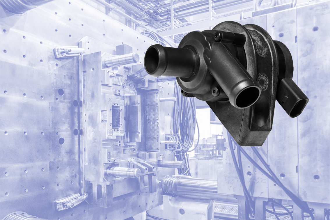
Plastic components in particular often have a high level of functional integration and associated geometric complexity. As a result, the manufacturing process and tools are equally complex. Error-proneness and unpredictable manufacturing problems are the result. These are, for example, core breakage, core displacement or over-critical mechanical and thermal loads on inserts. As a rule, experience-based troubleshooting is carried out in a trial-and-error process. This is associated with high costs for mold rework or even production downtimes.
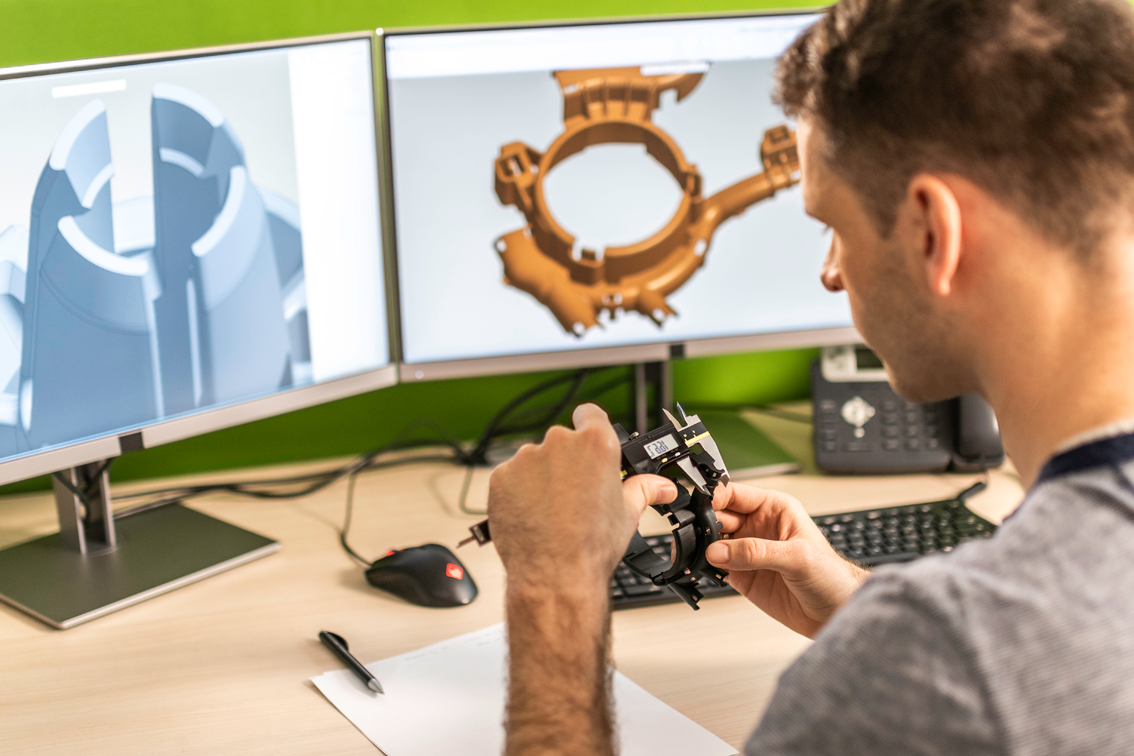
Deviations between nominal and actual geometry
As a rule, a structural simulation model is built based on the CAD nominal geometry of the component. However, this does not consider manufacturing-related shape deviations due to shrinkage and warpage during and after production. These can lead to the component being subjected to failure-critical stresses during subsequent assembly due to mechanical constraints in interaction with the operating loads. This is not obvious in a usually nominal geometry based simulation.
How does Converse solve the problem?
Converse provides the manufactured component with all relevant properties as a virtual component for structural simulation. This virtual component then contains the local microstructure if it is a fiber-reinforced component, for example, or the position of weld lines. The local microstructure is then transferred to the macroscopic component level within the framework of a multiscale simulation approach by automatically assigning the homogenized material properties associated with it to each finite element in interaction with MatScape. The component simulation can thus consider more realistic material properties.
For production-induced loads on tools or inserts, such as melt pressures and temperatures, Converse transfers the corresponding transient load curves elementwise to the respective structural simulation models. This enables the manufacturing process to be safeguarded by simulation.
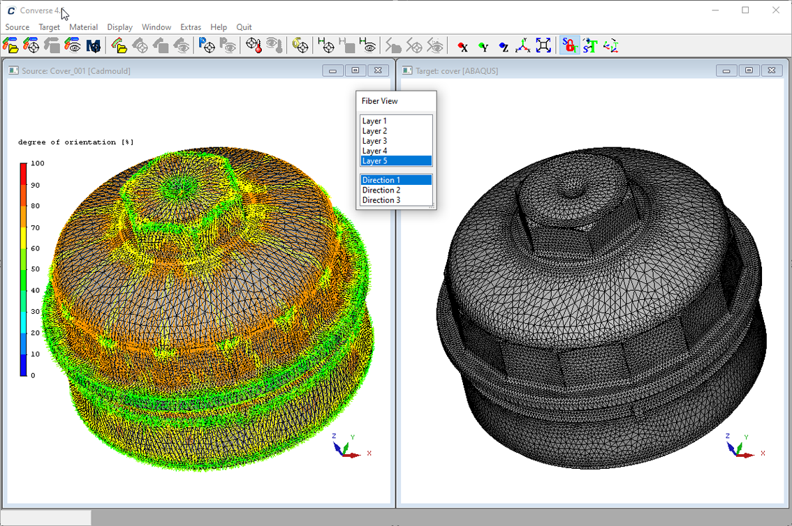
Converse requires the FE mesh and results of an injection molding simulation and the FE mesh of the structural simulation as input data. Different mesh topologies of the manufacturing simulation model and the structural simulation model can be processed. Converse uses mapping algorithms for this purpose.
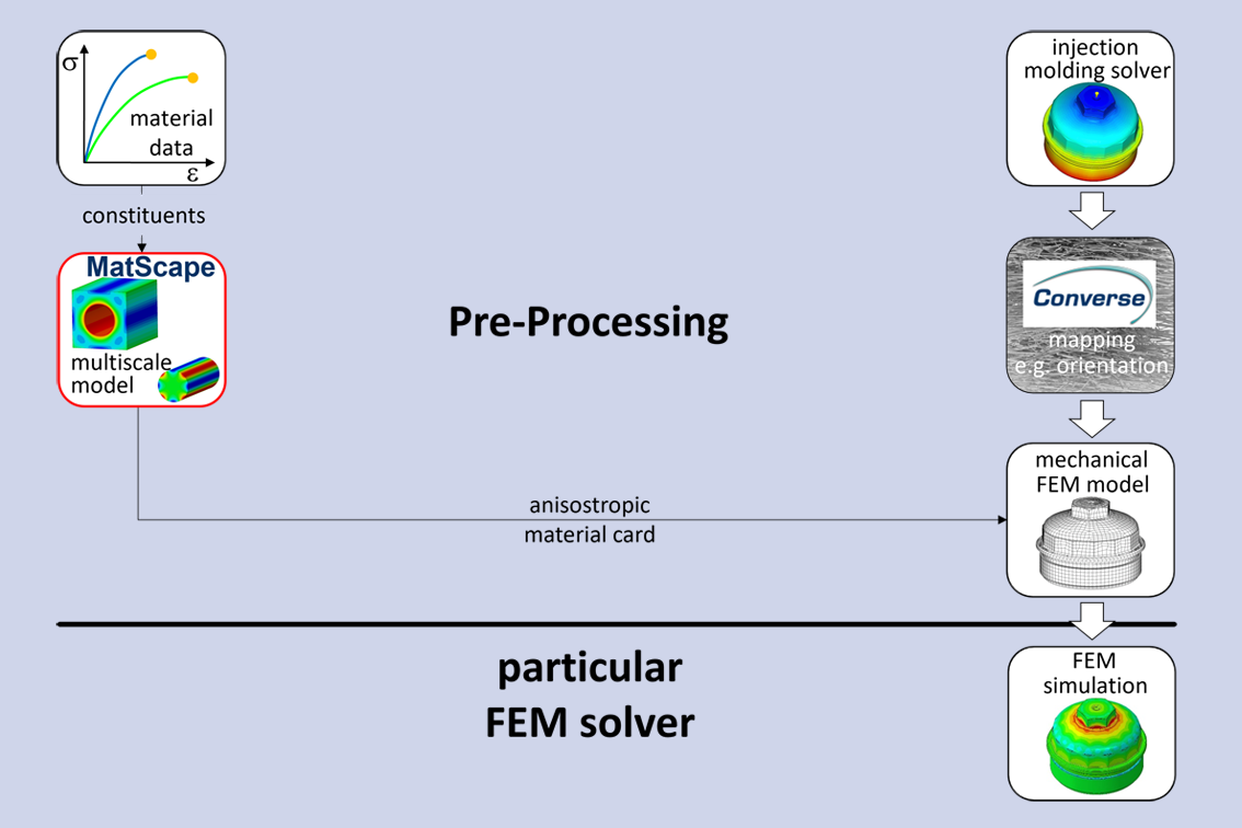
In interaction with MatScape, Converse creates ready-to-use FE model data that can be used without the need for external material models. The simulation is subsequently carried out independently of PART Software exclusively with the respective FEM program. This has considerable advantages in terms of speed and convergence of the simulation. Furthermore, the FE model data created once in pre-processing with the help of Converse and MatScape can be freely passed on and also used without usage of PART Software. This means that traceability and quality assurance of the simulation carried out is also possible later without limitation.
Some features & functionalities
- Mapping of manufacturing-induced local microstructures: fiber orientation, weld lines
- Mapping of manufacturing-induced time-invariant stresses on inserts and mold: melt pressures, temperatures
- Mapping of manufacturing induced shape deviations: Shrinkage and warpage, wall thicknesses
- Mapping of residual stresses
- Mapping between different FE mesh topologies
- Evaluation of mapping quality
- Consolidation of different injection molding simulation models into one structural simulation model (e.g. welded parts, assemblies)
- 3D visualization and standard manipulation of the imported models
- Automated generation of all required FE model data for the respective FE program
- Interfaces to commercially available injection molding simulation programs
- Interfaces to commercially available structural simulation programs
- Interfaces to commercially available fatigue solvers
- Integration with MatScape for the creation of part-specific anisotropic multiscale FE simulation models
- Integration with S-Life Plastics to perform anisotropic static strength assessment.
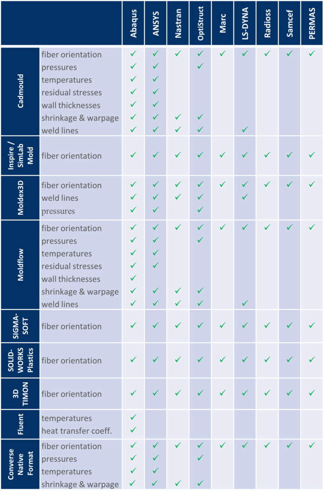
Features may vary depending on the FE program used. Details can be found in the table on the right.
Benefit
By coupling the manufacturing simulation with the structural simulation, Converse enables a more accurate simulation by considering a more realistic mechanical behavior of the component. The manufacturing of the component can also be safeguarded in advance by considering manufacturing-induced loads.
Converse reduces
- Costs for simulation execution (CPU time, license costs), since only optimized FE model data are created in the respective solver syntax (no co-simulation)
- Development time, since many variants can be simulated in a short time by using native FE model data
- Part and rework costs, since over- or under-dimensioning can be avoided through more accurate simulation results and the manufacturing process can be safeguarded
Converse increases
- Accuracy of simulation results, since component properties including manufacturing-induced influences (e.g. anisotropy, weld lines, shape deviations) can be captured
- Reliability of the simulation results, since FE model data are generated based on proper, standardized procedures
- Confidence in the simulation results, since the applied procedures are traceable and verifiable due to open data handling (human-readable FE model data)
Users say
For the simulation of short-fiber-reinforced plastics parts we use CONVERSE consequently. Due to that we are able to improve the quality of our simulations significantly. This helps us to design our parts considerably better.
The coupling of fill studies and FE analysis makes the predicted results more reliable. A detailed knowledge of the plastic material properties is important to design the products closer to the limits.
With CONVERSE it is possible to use the anisotropic material behavior resulted from fiber orientation. Identifying of manufacturing process induced weak points becomes possible and a more realistic behavior of the part can be predicted.
When we were looking for software that would help us to prepare our models for the simulation of glass fiber reinforced plastic parts, we saw that the Altair Partner Alliance offers CONVERSE, which is meeting our needs perfectly.
Get Converse
Please contact us for an individual quote without obligation
Converse can also be accessed through the Altair Partner Alliance, learn more here.