The FKM guideline [1] is the de facto standard for the strength assessment of metal components in general mechanical engineering. The guideline has been successfully used industrially for almost three decades. With a volume of approx. 230 pages, the static and cyclic strength assessment of metal components is presented in a comprehensive and structured manner. However, it is sometimes said that the guideline evaluates components too conservatively. This article shows that this perception is usually due to the fact that the potential offered by the guideline is not used. In particular, the guideline allows the exploitation of plastic load reserves in ductile materials in the static strength assessment. The guideline-compliant procedure for exploiting such reserves is explained. The paper is presented for non-welded components and local stresses as obtained from a FEM analysis.
Support factor confusion - A clarification of terms
The FKM guideline refers to two different support factors: the plastic support factor npl (also referred to as “section factor”) in the static strength assessment (chapter 3) and the cyclic support factor nσ respectively nτ (also referred to as “Kt-Kf-ratio”) in the fatigue strength assessment (chapter 4). Although static and cyclic support factors use similar terminology, they denote technically different phenomena and must therefore be considered strictly separately. The topic in this paper is exclusively the plastic support factor npl in the static strength assessment. The plastic support factor is defined as:
 (1)
(1)
The plastic support factor has a linear effect on the static component strength σSK:
![]() (2)
(2)
The plastic support factor can take the value of one as a minimum (material hardening not taken into account). This corresponds to no support effect, i.e. no utilization of plastic reserves of the material and thus design against the yield strength Rp. On the other hand, the plastic support factor can reach values >> 1 depending on the material, component geometry and load situation. It can thus increase the static component strength to a considerable extent. The first term of equation (1) evaluates the plasticity of the material itself, the second term the extent to which a critical component cross-section still has load-bearing capacity under the given load situation after exceeding the yield limit. First, in the following section we consider the second term of Eq. (1).
Plastic Collapse - Some Plasticity Theory
As a thought experiment, a component is loaded with a bending moment (Figure 1). In a first step, the load is applied exactly such that the yield strength Rp of the material is reached at the component surface at the position of highest bending normal stress (blue). In a second step, the bending moment is then increased further so that the yield strength of the material is exceeded at the component surface (red).
In practice, we now find for a ductile material that the component fails not at the bending moment at which the yield strength is reached on the component surface, as one might expect, but at a larger bending moment. What is the reason for this? Let's take a closer look at the stress profile: In the area of the component surface, there are high stresses beyond the yield limit, but in the interior of the component there are considerable areas where the stress is below the yield limit. This means that only comparatively small areas of the cross section under consideration undergo plastification, namely only those in the vicinity of the component surface. The remaining part of the cross-section is still purely elastically loaded. In this sense, this purely elastically stressed material supports the already plasticized cross-section area. This is also the origin of the term support factor. Such a supporting effect requires first that the material is ductile and second that there is a stress gradient into the interior of the component normal to the component surface.
The support effect is quantitatively determined by the so-called plastic notch factor Kp in equation (1), Kp is defined as follows:
![]() (3)
(3)
Referring to the example in Figure 1, the plastic limit load is the bending moment which causes the cross-section of the component to be completely plasticized. This means that the yield limit is reached at all positions in the cross-section. The elastic limit load is the bending moment that causes the yield limit to be just reached at the component surface. The ratio of the two load quantities is the plastic notch factor Kp. In other words, Kp is the factor by which the load can be increased compared with the initial attainment of the yield limit until the cross-section is completely plasticized (Figure 1).
According to the plasticity theory, the plastic limit load determined in this way is a lower bound of the load-bearing capacity. Plastic collapse of the component does not occur when the lower limit is reached. The lower bound of limit load is defined by the so-called (static) lower limit theorem, while the upper bound is defined by the (kinematic) upper load theorem. The critical limit load is located between these two bounds [2],[3].
According to the FKM guideline, it is therefore permissible, provided the material is sufficiently ductile and there is a stress gradient perpendicular to the interior of the component, to load the component until a critical cross-section is completely plasticized. This is a far-reaching concession with respect to an efficient design of the component using as little material as possible. Nevertheless, this is a safe design criterion since, as shown above, it is a lower conservative limit load bound.
However, these load-bearing reserves can only be taken into account if the plastic notch factor is also determined appropriately. Often this is not the case, Kp is not taken into account and set to unity. In this case, the static strength assessment is extremely conservative against the yield strength Rp of the material, as indicated by the minimum in Eq. (1) in conjunction with Eq. (2), because the first term in Eq. (1) is always > 1. The strain hardening factor fR was not considered. It takes into account a possible hardening of the material at high strains, which represents an additional design reserve. This will not be discussed further here.
It should also be noted that the plastic notch factor Kp should not be confused with the elastic notch factor Kt. The elastic notch factor is the ratio of maximum stress to nominal stress in a notched cross-section, which is different from the load ratio of the plastic notch factor. The plastic notch factor is defined in terms of load (not stress!). Now, in the following section, we consider the second term in Eq. (1).
Material toughness depends on the stress state
In everyday understanding, a material has a certain intrinsic toughness, depending on the temperature. This toughness can be expressed, for example, in terms of an allowable strain εallow. However, it is empirically known that the deformation capacity of a material is not a material constant, but depends on the state of stress in each case. The larger the hydrostatic stresses, the less deformable the material. This relationship is captured in the FKM guideline by defining the allowable strain in the first term in Eq. (1) as a function of the parameter h, the degree of multi-axiality (4):
 (4)
(4)
The degree of multi-axiality is the ratio of hydrostatic stress to deviatoric stress (von Mises stress). The relationship in Eq. (4) states that the allowable strain decreases with increasing multi-axiality. In particular, high degrees of multi-axiality occur in sharp notches. This leads to the fact that actually ductile materials usually fail brittle in sharp notches. This phenomenon is also referred to as stress embrittlement. Thus, the allowable strain of the material is a local parameter that takes on a different value at each position in the component (FE node) as the stress state changes.
Another function of the first term in Eq. (1) is the consideration of the real elastic-plastic material behavior. This is done here by a Neuber correction of the linear-elastically computed stresses. This is the reason for the square root (Neuber hyperbola) in the first term. However, this aspect will not be discussed further here.
And now all together - The twofold criterion
Via the minimum in Eq. (1), a twofold assessment is performed. Depending on which of the two terms is smaller, either a local material strength limit (term 1) or a global limit load (term 2) is decisive for the local static component strength. The more critical situation decides. Thus, the strength or strain criterion in term 1 refers to the local exceeding of the material's deformability, whereas the global limit load criterion in term 2 restricts the unstable plastic collapse of a cross-section. The relationship is visualized in Figure 2.
The lower diagram shows a material curve normalized to the yield strength (stress-related). The upper diagram is a so-called component yield curve (load-related) normalized to the elastic limit load, the denominator in Eq. (3). Two materials of different toughness, expressed in terms of the allowable strain εallow, are considered. The component strength is limited for material 1 with the lower allowable strain by the strain criterion (term 1). Here, the allowable strain is exceeded in the notch root. In material 2, on the other hand, with higher allowable strain, the component strength is limited by the load-bearing capacity of the cross-section under consideration (term 2). The material as such would still have had plastic deformation potential.
With the concept of local component strength, the FKM guideline thus moves away from the understanding of an intrinsic uniform strength per material. Instead, the component strength in the sense of the plastic support factor of the FKM guideline is to be understood either as the strain limit of the material or as the limit load of the component. The determination can be carried out automatically per location in the component (FE node) using the formalism of the guideline. However, a practically feasible application of the concept requires an automated software-based procedure, as implemented in S-Life FKM. The double criterion Eq. (1) including the calculation of the stress-dependent allowable strain is carried out automatically per surface node of the FE model, and the resulting local static utilization ratios are displayed as a contour plot (Figure 3). A comprehensive numerical report of the assessment enables the detailed analysis of critical nodes and the identification of which of the two criteria was decisive.
There is no free lunch
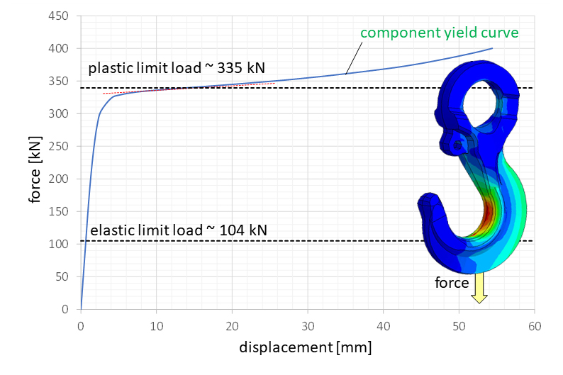
On the one hand, the concept of the plastic support factor via the twofold criterion has a certain elegance. On the other hand, its practical application is hindered by the fact that, in general, there is no simple algorithmic procedure for determining the plastic notch factor Kp in the second term of Eq. (1). According to the FKM guideline, the plastic notch factor is to be determined via a nonlinear FEM analysis with an elastic-ideal plastic material model. This can then be used to determine the component yield curve (load-related), from which the limit load can then be obtained. Figure 4 shows an example of this for a load hook.
On the one hand, a nonlinear FEM analysis requires numerical effort. On the other hand, when complete cross sections are fully plasticized, as is by definition the case when determining the plastic limit load, convergence problems can occur during the simulation. Also, not everyone has a FEM program with the ability to use nonlinear material models. For special cases, when the reference cross sections can be defined as nominal cross sections and the load can be defined as far as possible as one of the basic stress modes, the plastic notch factor can be estimated conservatively according to the guideline [1, chapter 3.3.1.1].
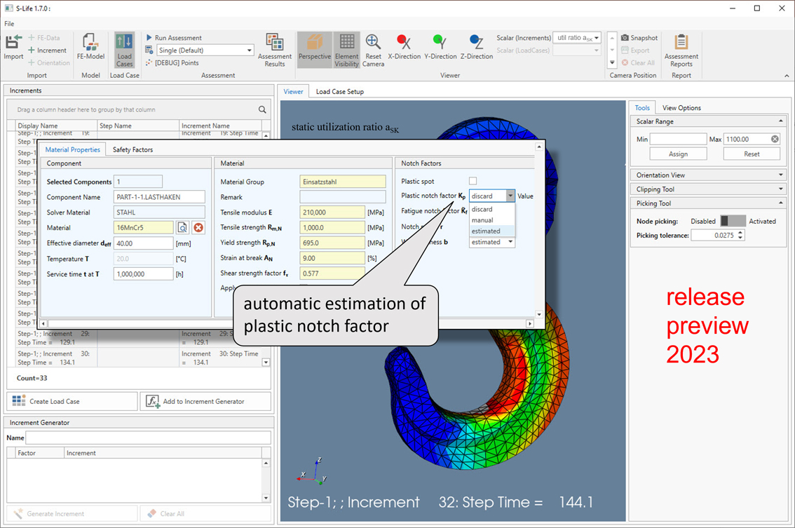
In the lack of a satisfactory solution for the straightforward determination of the plastic notch factor, an improved procedure has now been implemented in S-Life FKM (Release 2023). This allows an automatic estimation of the plastic notch factor Kp and thus also of the overall plastic support factor npl for each surface node of the FEM model (Figure 5).
Conclusion
In the static analysis of ductile materials, the FKM guideline offers extensive possibilities for exploiting plastic material and limit load reserves. A prerequisite for this, however, is the determination of the plastic limit load. In most cases, this is only possible by means of a non-linear FEM analysis, which involves considerable effort. With S-Life FKM, a simplified estimation of the plastic support number can already be performed automatically. An improved procedure will be available in S-Life FKM in 2023.
With the help of S-Life FKM, the processing of local stresses obtained from FEM analyses with regard to static strength and fatigue strength in accordance with the FKM guideline will be performed almost at the push of a button. S-Life FKM requires stresses from a structural analysis. Interfaces exist to various FEM programs. As a result, among other results, the static and cyclic utilization ratios of the component are displayed as a contour plot according to the FKM guideline.
References
[1] Analytical Strength Assessment of Components in Mechanical Engineering in its 7th revised edition, Forschungskuratorium Maschinenbau, VDMA Verlag, Frankfurt am Main, Germany, 2020
[2] L. Issler, H. Ruoß, und P. Häfele, Festigkeitslehre - Grundlagen, 2nd, corr. Reprint 2006 ed. Berlin Heidelberg New York: Springer-Verlag, 1997.
[3] „Plastic limit theorems“. Wikipedia. Accessed: February 9, 2023. [Online]. Available at: https://en.wikipedia.org/wiki/Plastic_limit_theorems
[4] B. Hänel u. a., „Verbessertes Berechnungskonzept FKM-Richtlinien“, Forschungskuratorium Maschinenbau e.V., Frankfurt a. M., Final Report FKM Project No. 282 Issue 306, 2010.
Author
Dr. Wolfgang Korte is Managing Director at PART Engineering GmbH, Bergisch Gladbach, Germany